Lotus Europa S1: Repairing the chassis backbone
Hello everyone,
it’s been a while since the last update, but I have been working harder than I have been updating the blog. So bear with me, this is going to be a long blog entry.

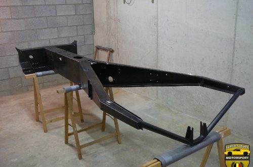
This is our subject for this post, it’s the backbone part of my original 1967 Lotus Europa chassis. What you see here, is (what’s left of) a backbone style chassis made up of folded sheet metal sections of 1.6 mm thickness. Before I started I placed the chassis on my concrete floor that I know that’s completely level. I used some wood blocks and spacers to prop the chassis in a solid an level position. This was the chassis won’t flex or bend when I try to weld it. If everything stays level while cutting out the sections, I should finish with a completely straight chassis.

These are the repair panels that I had folded up by a friends friend. I had to wait quite a while to get them back, because he was very busy and didn’t have the time to do them right away, this is also the reason that there’s a lot of surface rust on the repair sections. Repairing everything in sections will make sure that the chassis is straight, because I have reference points of the original panels all the time when welding them in.

You can see that I’ve divided the backbone in different section depending on the amount of repair needed.

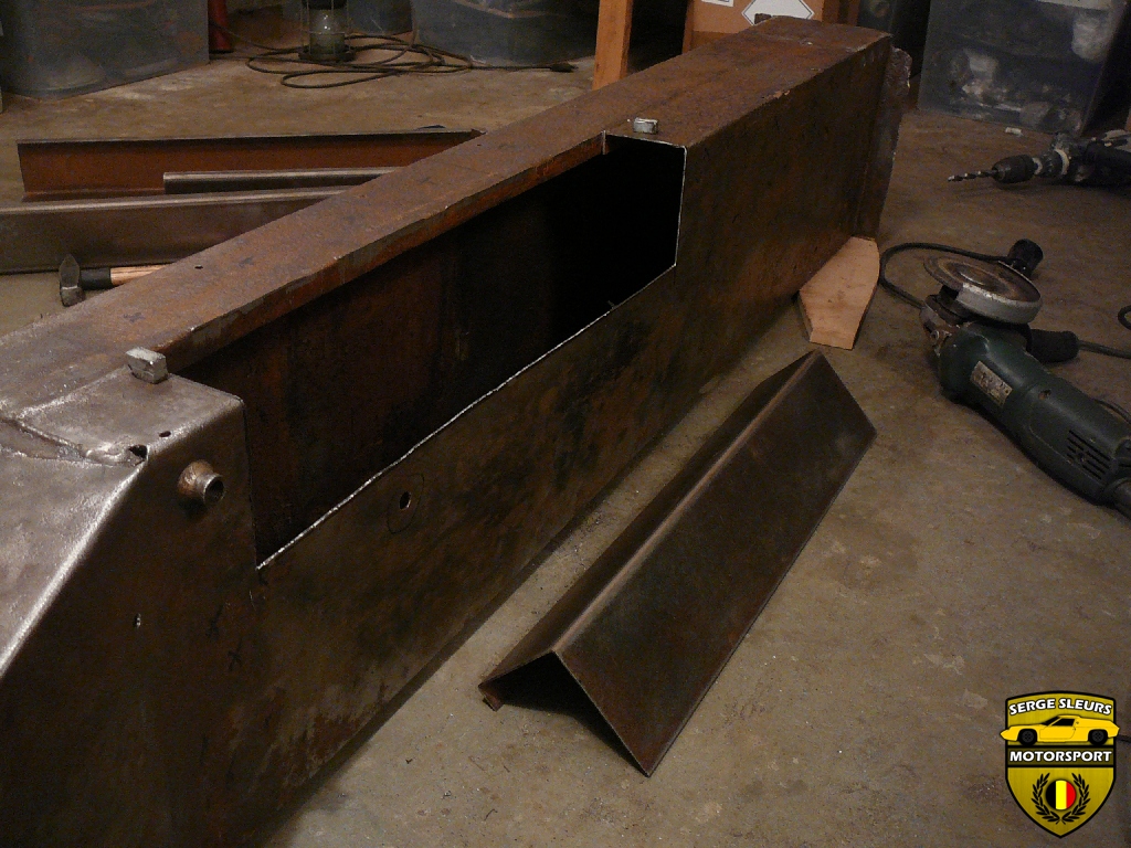
I started by cutting out the rusted section without removing the seam welded lip. Most of the cutting was done with a jigsaw.

Then I used a chisel to get the welded lip off of the chassis, after this I used a jigsaw to cut the lip off. While I had access I tried to clean out as much of the inside of the chassis as I could, because there was quite a bit of dirt and rust in there.

This is the repair section that I made to repair this part of the chassis. You can also see the grinding disc on the angle grinder that I used to grind out the hole to get a good fit for repair section. Because the repair sections aren’t 100% accurate I cut these sections in 2 pieces. One part with the lip and a horizontal section and the other part with the vertical, the bend and the horizontal section. This was needed to trim all of the pieces to an exact fit and this was also necessary to be able to weld the lip on the inside of the chassis.

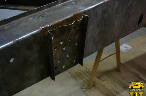
In the last picture you’re able to see that the flat side of the chassis was warped. This happened because a previous owner welded on a new bracket for the clutch cable. I used a piece of angle iron riveted to the side of the chassis to straighten this as I welded the new section in place.

This is the inside of the lip that needs to be welded from the inside of the chassis. On the right you can see the top part of the repair section that I’ll weld in first, then I can weld the lip on the inside before I’ll weld the side section in place.

I tacked the first part of the repair section in place.

As usual I used my TIG welder set on +/- 62 Amps and I used the trigger on the torch, because it wasn’t easy to operate the footpedal.

In this photograph you can see that I’ve mocked up the fitment of the second part of the repair section, ready to be tacked into place. The angle iron that I used to straighten that part of the chassis is also visible.

Here I’ve tacked everything and It’s ready to be welded.

I stitch welded everything to start, this made sure that the heat was evenly distributed, because these panels will warp quite badly if you don’t take care.

The welding is finished and I removed the angle iron. The only thing to do now, is to fill the holes that I used to rivet the angle iron to the chassis.

By using a straight level, I checked if my little trick with the angle iron has worked. And it has! The panel was very wavy before I started and it has straightened out very nicely.


This is a before and after shot of the rivet holes that needed to be filled in. I used an aluminium backing plate to facilitate filling in the holes.

Once that side was finished, I opened up the other side of the chassis to receive the same treatment. While this side of the chassis was opened up I tried to remove as much rust as I could from this opening.

Everything tacked into position and ready to be completely welded in.

Before I started cutting everything was straight and level and a soon as I cut out one of the end sections a lot of internal stress was set free and the chassis opened up a little. By using various clamps and a jack I made sure everything was straight again before I started welding in the new piece.

By the time I got to the front repair sections quite a bit of time had gone by (due to exams etc.) and I had treated myself to some new welding magnets. I used these (together with some of my rare earth magnets to test fit the new section.


All tacked up and completely welded in the second photo. In the second picture you can also see that I tried to preserve as much of the original chassis as I could (Everything is only original once.) But this made everything a little bit more difficult, because of the position of the weld seam. There is always going to be a little bit of warping, because this isn’t something that’s clamped that easily. The complete chassis is still as straight as an arrow, just the side sections of the chassis have bent inwards just very slightly on the weld seam.

Because I am somewhat short of stature, I needed to modify the pedal mounting points on the chassis. A Lotus Europa S1 has fixed seats that are moulded in the firewall of the bodyshell. The only adjustment that you have are the pedals (about 1 1/2″ – 37 mm) and the steering column. But because I fall below the adjustment range of the pedals I needed to make some more mounting points for the pedalbox. All the mounting points were drawn out and tested before I drilled them out. These modifications give me around 4″ or 10 cm of extra adjustment range on the pedalbox.

While I had the chassis on stand I quickly removed the bulk of the weld beads, but they needed to be dressed further.

This is the inside of the chassis, after I removed the last chassis section that needed to be repaired. Here you can see the nuts welded to the back of the holes. A bolt is threaded in from the outside of the chassis to mount the pedals. To make sure that the nuts where centered on the holes I threaded in a bolt before I welded them on.

The last section was also the biggest one, so the access to the chassis was the best at this moment. I used this moment to remove all of the rust on the inside of the chassis and then to paint as much of the inside of the chassis as I could. I rolled some balls of masking tape to protect the threads of the nuts . The black stuff that’s painted on the surface is FE-123 Rust Converter from Rust.co.uk. It’s white when it’s in the can and it turns black when it’s done its magic and the rust has been converted to a rock solid black surface that’s overpaintable. Before I used the converter I removed as much rust as I could using wire brushes, sandpaper and wire wheels on an angle grinder.

Once the rust has been removed I painted the inside of the chassis (except the edges that still needed to be welded). I used black Epoxy-Mastic 121 chassis paint from Rust.co.uk. This paint comes in two parts and needs to be mixed in a 1:1 ratio. I tried pouring the paint, but this went horribly wrong, you can’t get small quantities of this paint mixed accurately.
The solution that I found worked best was using syringes of 50 ml to get the paint out of the can and into a mixing pot. This way the quantities are absolutely spot on. You can buy these syringes at some paint stores, but I recommend going to the pharmacists and buying some there, you’ll be amazed at the price difference for almost the same syringes. I bought these at 73 eurocents a piece, while the paint store was asking €15 for one! I did find that you couldn’t use a syringe more than twice (or maybe three/four times), because the paint is very viscous and very sticky and the rubber would come off the plunger. But at that price you could buy a couple without hesitation.

This is after the first coat and you can see that it covers reasonably well, but it definitely needs two coats. The paint is quite thick to brush on, but it comes with a small bottle of thinners to thin it if you like it thinner or if you wanted to spray it.

A second coat makes sure everything is covered. Epoxy-mastic is a type of paint that’s also used on some oil rigs in the North Sea, so it’s one of the best anti-rust paints on the market, so two coats will protect the inside of the chassis perfectly as the majority of the rust was on the outside of the chassis. Getting my brush in the chassis section on the right wasn’t easy and I was covered in paint trying to make sure I had painted everything of the little chassis bulkhead and all of the little nooks and crannies.


Once the paint had dried it was time to weld the last repair panel in place. I used a variety of clamps and a couple of levels to make sure everything was arrow straight before I welded everything.

On this side of the chassis, the repair work needed was more substantial so less of the original material remained. While more of the original chassis was removed, this made welding this quite a bit less stressful. Because the weld seam wasn’t in the middle of the panel, but closer to the folded edge, the weld didn’t have the chance to bent slightly inwards. I was almost going to cut out the other side of the chassis and start again, but I was able to restrain myself.

All the chassis sections were welded in place and the only join that needed to be welded was the top seam in between the two sections. I clamped the seam down to make sure it was straight and then I welded it up.

Here you can see the finished weld between the panels. I’ve also started to clean up the welds a bit more so that you won’t notice that the chassis consists of a lot of different sections.

This is a picture that proves my point about having a very straight section if the weld seam is close to a rigid edge.

The caster angle of the front suspension is built into the chassis. This means that the front T-section is welded to the backbone at a 3° angle for an S1/S2. TC’s have a smaller caster angle. Having replaced the front edge of the backbone, I needed to replicate the angle. On the top of the chassis you can see what’s left of the folded lip that was originally used to weld the backbone to the T-section. I am not going to use the lips, because this meant that the backbone was only welded with these lips, and once the metal was fatigued a bit, there was quite a lot of play in the joint between the backbone and the T-section. I am making sure that the backbone has a solid connection with the T-section. The scribe line should be 3°.


Because I had to compensate the lip not being there, I had to fold the lip down and weld up the gap, so I could use the metal from the lip to fill the ‘missing’ metal of the chassis.

Double checking the 3° angle with the original chassis section after I made the cut on the scribe line.

Making some little tweaks to make sure that the edge is very straight, so I can do a fillet weld between the backbone and the T-section.

On the side with the large repair section, I had to weld the threaded insert for the handbrake pivot onto the new chassis section.

Now the chassis was back complete I could drill the holes for the brake and clutch pedals. I used the original holes in the section that I cut out of the chassis to calculate the relative position of the brake/clutch pedals to the throttle pedal. Then I marked out where the new holes needed to go.

Everything is marked out, a big hole for the pedal pivot and a small hole for a screw to hold the pivot in place.

I used a centre punch and a couple of imperial sized step-drills to drill out the holes. The big hole was exactly the size of my largest step-drill, 3/4″.

The finished product.

Before I painted the rest of the inside of the chassis I welded some M6 nuts on the outside of the chassis in some strategic locations to be able to use these a grounds for the electrical system. I used mild-steel nuts, but hindsight being 20/20, maybe I should have used some stainless nuts to weld onto the mild steel chassis using a different TIG filler wire. Painting the inside of the chassis was quite a challenge. I had to paint everything that was near a weld joint through the top opening in the chassis and the end opening of the backbone, but I got there in the end.

All the welding on the backbone and the Y-section was finally finished, so I got some help and we carried the chassis out of my basement workshop. It was the first time in a year and a half that the chassis has seen some daylight.

I used some flapdiscs to finish dressing the welds and some wire wheels to get rid of all of the surface rust.

I suspended the chassis with some wire in my dad’s garage, because I needed a ventilated area to paint the chassis. The blotchy finish that you see in this picture is the rust converter doing its work on the remaining surface rust, once it had finished it was flat black.

I mixed up the Epoxy-Mastic using my syringe method. You can also see my tools for the job, some cheap round brushes for difficult to reach areas and some foam rollers for the flat sections.

This is the chassis after the second coat has been applied, the paint is still wet, hence the shine. The backbone part received a thin third coat, because there was a little bit of paint left over.


The finished product looks pretty good. The light reflection shows all of the dents and dings in the chassis, but this work wasn’t about making things look pretty, but to make them stand the test of time. I did all of the rust repairs to make them strong and functional, aesthetics came second. Epoxy-Mastic is one of the best products to use, the paint lasts for at least 10 years in the middle of the North Sea, so it will make sure that the chassis lasts another 50 years. The downside is that Epoxy-Mastic isn’t UV-stable, so the colour will fade if exposed to sunlight.
There is some work left to do on the chassis, the front T-section needs to be finished and attached, there are various holes that need to be cut and maybe some welding needs to be done, but the chassis is protected from the elements and if any paint needs to be removed, it will be very limited. After all this chassis work has been completed, I will make the chassis look the part as well. I will use a skim coat of filler to smooth’en the dents and I’ll spray it in a satin black 2K paint that will be UV-stable and will be as smooth as a baby’s bottom.
Thank you for sticking with me, I know this was a very long winded post, but at least I got a chance to update my progress. Currently I am building my own front T-section, because the original one was too far gone, but I’ll update this as soon as possible.
Kind regards,
Serge