Lotus Europa S1: Adjustable lower links
Hi everyone,
In this post I’ll show you how to make your own adjustable lower links for the rear suspension on any Europa using rod end bearings. You can also use this guide to build any turnbuckle linkage, because that’s what this essentially is, just made to fit the Europa rear suspension.

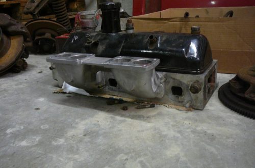
This is a picture of the original lower link that was on my S1 when I bought it. As you can see it isn’t straight anymore and it has a bend in it. This is usually because some people would use the lower links as a jacking point, but this isn’t a good method.

Because of this the lower links will not conform to the original dimensions (as per the workshop manual). So these needed to be replaced. There are a couple of options, first of all you can buy new original ones, secondly you can buy adjustable ones with polyurethane bushes or adjustable ones with rod ends.

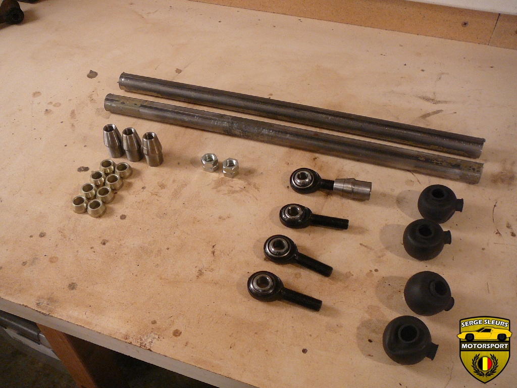
But we’re going to build adjustable lower links with rod end bearings. In this picture you can see every component that we’ll need to build these. Rod ends (left- and right hand threaded), locknuts, threaded inserts, tubing (with a matching internal diameter for the inserts) and some dust boots. I got all of this at McGillMotorsports.

Before we can begin cutting some tube, we need to calculate the length of tubing that we need to make our adjustable links the right length. We’re using the Lotus Europa workshop manual from Jerry’s website. From this drawing we can calculate the lower link length from eye to eye, this is 484mm.

I’ve calculated that we need 364mm of tubing, plus 120mm of threaded inserts and the adjustable range of the rod ends, to give us an adjustable lower link that will give us the option to make the length longer (more negative camber) and shorter (less negative camber). You need to keep in mind that you always want at least 1.5x the major thread diameter of your rod end threaded into your threaded insert to assure that everything is up to the task. On my lower links this would be 19mm (1.5x 1/2 UNF).

Using masking tape around the tube will make sure that your cut is 90° straight all the way round. If your tape doesn’t line up when you wrap it around you’ll know that it isn’t correct. You can use a normal hacksaw to cut the tubing, I used my angle grinder.

I didn’t cut too close to the tape, I trimmed everything right up to the tape with a file.

Then it’s time to draw the width of the flange of the threaded insert on the tape. This will help you decide where you want to drill the holes in the tubing for the plug welds. I decided on three plug welds per threaded insert.

I used a center-punch to position the drill bit, then I used my cheap Aldi pillar drill to drill some pilot holes in the tubing.

Afterwards I used the pilot holes to drill 10mm holes in the tubing for the plug welds.

You have to deburr the holes for a couple of reasons. The first one, is that the threaded inserts will not fit the inside of the tubing. The second one, it that it makes plug welding all the more difficult (especially if you’re using TIG like me).

Once the insert fits, I made a little ‘jig’ with some welding magnets to hold the lower links steady while I welded them up.

I started by welding the seam between the insert and the tubing.

Then I plug welded the holes. Using TIG to plug weld isn’t the easiest, but it went OK after some practice attempts. You start by welding the outside of the hole in the tubing to the threaded insert below.

Then you fill the hole in to make in an even surface.

After this I used an angle grinder with a flap disc to grind it all smooth so that it looks like one smooth part instead of a couple of sections welded together. I finished everything of with some files and some 80 grit sandpaper.

When they are assembled they look like this.

As you can see, one smooth section. Obviously they still need to be painted, but I’ll to that when I paint the other suspension components.

This is the money shot! One of the threaded inserts has a groove machined in to them, this indicates that this is a left hand threaded insert. Because we have a left and a right hand threaded rod end on each end of the lower links, we can adjust the length of the linkage while it’s on the car. Just loosen the lock nuts, twist the link and the length changes. You will have to jack the car up to do this.

This is one of the dust boots installed. These will make sure that a minimum amount of dirt will get in the bearings, because these are out in the open on a Europa, this way the bearings will last quite a bit longer. You can install these dust covers by using two pliers to open the hole in the bottom and just pull it over the rod end.
So this is how you build the adjustable lower links, I hope you enjoyed the post and that you might have learned something. If you have any questions, don’t be afraid to contact me via the link at the top of the page.
Enjoy & Share,
Serge