Lotus Europa S1: Fabricating a new front T-section
Because I decided that I didn’t want to buy a new chassis or any chassis sections to repair my original (but very rusty chassis), I had to fabricate a new front T-section out of a 1.6mm steel sheet. It has taken me a couple of months to get to this stage because I can’t spend much time on the car at the moment, a couple of hours a week maximum. Progress is slow, but in this post I’ll show you what the end result looks like and how I got there.


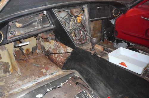
These three photographs are to remind you of what the original T-section looks like when I cut it off of the rest of the backbone. The bottom 10cm is completely gone and rust had started to set in between all of the spotwelded seams.

My initial plan was to repair the original T-section, cutting out all of the rust and replacing it with new steel. But before I started to cut into the T-section, I needed to make some jigs of the suspension pickup points so that I could replicate the suspension geometry onto my new parts. Additional to the jigs you see in the photo I made another black one as you see there. These jigs fit onto the front and the rear of the T-section and these will locate and fix the pickup points in relation to each other.

This is what the original T-section looked like when I removed the rusted out bottom and was drilling out the spot welds for the internal strengthening plates. By this stage it dawned on me that the front was beyond repair. It would be far easier and also far more durable to fabricate a new T-section from scratch. So that’s what I did.

I started off with a 1.6mm steel sheet that I bought locally for €30, the chassis plans from Jerry’s website and the original T-section to take measurements from. I quickly found out that I couldn’t trust the measurements on the chassis plans, because they were quite a bit off. I used the plans as a guide but I used the original T-section to validate all of the measurements.

Because I don’t have a sheet metal brake to bend all of the sections, I had to improvise. I divided the T-section in smaller panels that I could fabricate with the tools I had at my disposal. The first panel that I wanted to make was the top section. I started off by cutting out the basic shape with a jigsaw.


I made all of the folds by clamping the steel sheet into a vice and hammering it down with a big hammer.

As you can see, they match perfectly. Also in this picture, you can notice the small slots that I had cut into the sides where the flanges will be folded downwards. I did this because I can only bend small sections at a time.

I folded the flanges downwards with the tools you see in this photograph: two different hammers, a piece of steel box-section and a vice.

Here you can see that I had completed one flange, with the other one still to go. But you get the idea on how labor-intensive this relatively easy job gets when you don’t have all of the fancy tools.

Throughout all of the metalworking a lot of my time was spend by completely drawing out the entire chassis sections on the steel sheet and then cutting it out with my jigsaw. I didn’t use any markers, bit I chose to scribe the cut and fold lines into the steel for added accuracy. To cut out the holes I used a bi-metal hole-saw set on a low speed electric drill.


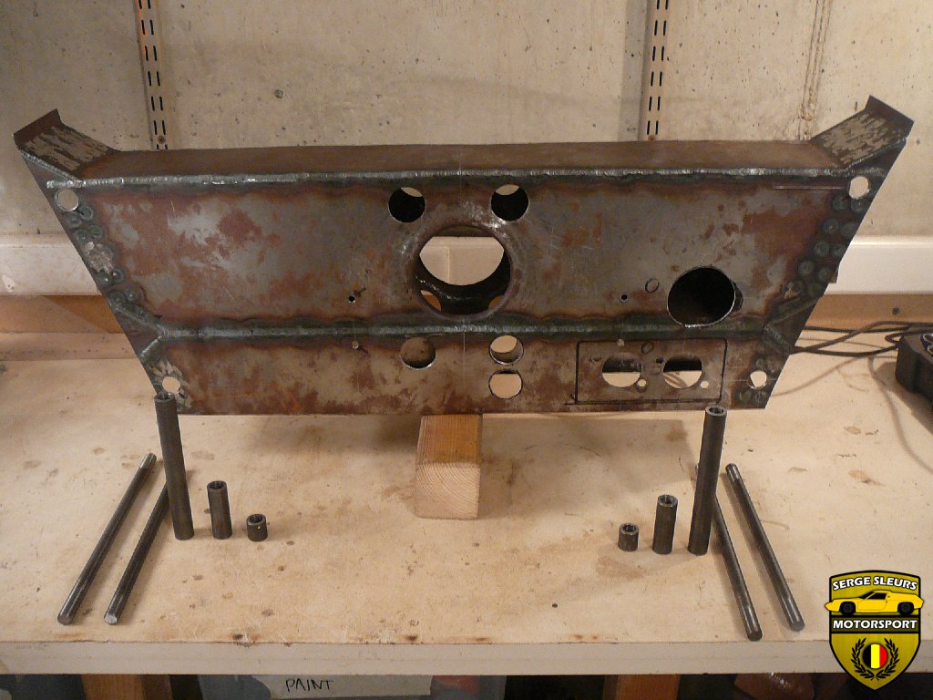
These two photographs show the rear panel of the front T-section with the needed holes already cut out. I opted not to cut out the holes on the right hand side, although the original T-section did have most of the provisions to be both right and left hand drive. You can also see me trying to fit the top and the rear panels together to double check as I finished each panel.

The upper (shown) and the lower front panels were made in the same fashion.


Because I didn’t have a flaring tool or a shop press that I could use to fabricate the flared hole in the middle of the T-section, I cut out the flared hole from the original one and welded it onto the new panel. Once the welds are ground off, no one would know the difference.


Remember those slots I had to cut into the flanges to be able to fold the flange in small increments on my vice? This is how I got rid of them: I welded the slots up while I clamped the panels onto a flat surface and afterwards I smoothed out the welds. It’s amazing how rigid the panels become once the flanges were welded up, that fold in the panels make all the difference.

Inside the original T-section there were some strengthening plates that are plug welded between the front and rear panels. I replicated those as well, you’ll see these in some of the following photographs.

Next up were the side sections. These connect the front and rear panels and also give a lot of strength while locating the suspension pickup points.

While it was possible to make the panels with my vice and a hammer, I needed to get something that could help me make all of the folds. This is a vice mounted folder. You clamp the piece of metal between the jaws and close the vice, the jaws push the metal in such a way that a perfect fold is formed. While this isn’t some magical tool, and it still as a lot of downsides, this helped me quite a bit. It isn’t too expensive and the limit of the sheet thickness depends on the strength of your vice.


It took me a while to figure it out, but once you have the hang of it (and know what folds you have to make first) you don’t have to drill to many slots. You can see the difference between the first and second one and the amount of slots that I had to cut in the first one.

Now I had to weld up the side box sections.


These are all of the parts that form a complete front T-section stalled out on the floor and then clamped together to check their fit. Once checked, it’s time to weld everything together.

I started off by tacking the side panels into the large rear section.

This facilitated the spot-welding of both panels. I did some test pieces before I started and I did some destructive testing. All of the steel sections broke before the welds did, so I deemed the tests successful.

I did all of the spot welds with my TIG welder.Using clamps that allowed me to weld in between the clamping forces made sure I got a good contact patch between the panels. The small grey piece of metal that’s clamped between the clamp and the panel is a small strip of 2mm aluminium that I used as a backing plate to make sure that I didn’t blow through both steel sheets. This allowed me to use the full 200A of my Stahlwerk TIG welder in a 8 second burst to melt both steel sheets together without blowing through.

Here you can see the full penetration that I got by spot-welding.


Next up, the top panel. First, checking the fit and lining everything up. Then I clamped everything in place and tacked the top edge of the rear section to the top panel. And lastly I spot-welded the “wing sections” to the side panels.

The front of the T-section consists of two panels that are spot-welded to each other using an internal flange. I welded these together on my workbench before spot-welding them onto the rest of the T-section.


Once these to panels had been welded together I used the same method as explained above to weld the front panel on.


Remember the internal strengthening plates that I mentioned before? This is how they are welded in. On one side they are welded to the flange between the two front panels and on the rear of the front T-section they are spot-welded. Because I couldn’t clamp these into position I used a method called plug-welding. I drilled some 10mm holes into the top panel and welded the edges of the top panel to the lower panel inside of the hole. Then you fill the hole with filler rod so you can grind the weld flat afterwards.

Now all of the spot-welding was finished, I was sure that the structure was very stiff and it could resist a bit more heat. So I welded up all of the seams that I had created by not being able to fold the large panels.

Of course some of the seams had to be welded from the start, like the one between the two front panels. On the original chassis they were only welded every couple of inches, I opted to weld the entire seam from left to right.

The basic structure has been completed at this point. We can compare the new T-section on the left versus the original one on the right.

There are some holes that I didn’t want to drill before the panels were welded together because their position is crucial to the behavior of the car once finished. The mounting for the steering rack is one of those things. I mounted the (unrestored) rack onto the original T-section to check out any problem areas and to make measurements.

The holes on the right hand side aren’t any problem.

But on the left hand side I also had to drill the holes to accommodate my new twin master cylinder brake setup. Therefore I needed to make sure nothing would touch. As you can see I decided on mounting the master cylinders at an angle to create a bit more space between the steering rack and the master cylinders.

I also had to enlarge the hole for the steering column a little bit because I am switching to a forged U-joint for the steering column in stead of the one with the rubber bush in it and the new U-joint would hit the front panel if mounted. The two holes that I was drilling in the middle of the front panel are holes for the oil cooler hoses for a front mounted oil cooler setup.

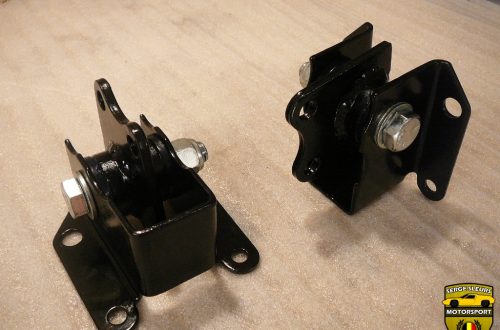
To mount the master cylinders i made a 3mm thick plate with the bolts already welded on. This will make mounting them a lot easier in the future.


Now the crucial part! Making sure that the suspension geometry is completely up to the dimensions mentioned in the workshop manual. I used the jigs that I created from the original T-section to drill some small pilot holes.

These pilot holes were used to drill bigger holes (about 1-2mm bigger than the steel tubes that are the pickup points) with a hole saw.

I got the 1/2″ ID tubes from Richard at Banks because I couldn’t find these locally. The pickup tubes were cut to size, because S1 pickup points differ from the later S2 pickup points in that S1’s use a narrower upper wishbone. The big tube goes on the bottom and the two smaller ones are for the top one.

I lined up all of the tubes and made sure that their stick-out is correct while the jigs make sure that the geometry is spot on. I placed the suspension pivot pins into the tubes to align them.

Once this was all quadruple-checked, I tacked the tubes onto the T-section.

The process was repeated on the rear panel.

With the jigs in place I completely welded the tubes in place.

This is what it looks like once the tubes are welded on. Because I welded everything with as much of the jigs in place as possible, the jigs still fit without a problem.


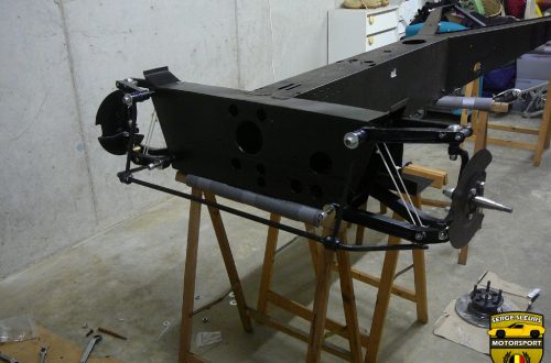
These last few photographs show the new front T-section roughly mocked up against the repaired backbone. In the next fase of chassis repairs I’ll be welding the front T-section to the backbone while welding in the bottom plate for the T-section.
I know this was a long-winded post, but I hope you’ve enjoyed it anyway. I tried to include as many photographs as I could to make it a more visual experience.
If you have any questions don’t hesitate to contact me using the link on the top of the page.
Kind regards,
Serge