Lotus Europa S1: Restoring the rear suspension
Hi everyone,
In this post we’ll go over the rear suspension, what parts to keep, restore or get rid of.

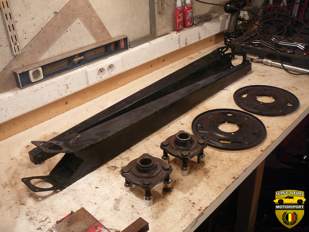
You can see all of the components laid out on the floor of my workshop. In the back you can see the radius arms, they need quite a bit of work, but they will be re-used.

The coilovers (springs & dampers) will be replaced by some very advanced coilovers and the lower links will be replaced by my own adjustable version.

The aluminium bearing carriers have had a hard life, they look terrible, but we will take care of that. We’ll also restore the back-plates for the rear drum brakes as well as the rear hubs.

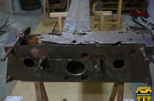
While we will be re-using the back-plates, we will discard the rest. The drums themselves (not pictured) had grooves in them, the adjusters were stuck, the slave-cylinders were seized and the shoes were worn down. This picture show the original brakes prior to dis-assembly.

Once disassembled, we can sort all of the pieces out. I always hang on to the original parts (even though they can’t be used anymore), just to be able to check the fitment of the new parts should there be a problem while reassembling everything. I put all of the components in a labeled zip-lock bag before storing them in the plastic container labeled ‘rear suspension’. This way I can quickly find all the parts that I need. I’ll remove the rust from the backplate using a combination of soaking in vinegar and a wirewheel on an angle grinder.

These are the new rear drums, they will be painted with the same paint as the rest of the rear suspension parts. Be mindful not to paint the inside of the drums, otherwise you’ll run the risk of having your rear brakes not working because everything is covered in paint flakes after it has burned off.

This is what the rear bearing cariers looked like, a mess. Everything was covered in dirt, dried up oil, rust, corrosion and the bearings were seized inside of them.
no images were found
I started off by removing the bearings from the housing. The easiest way to do this, is to put a socket through one of the bearings and hammer the opposing bearing out. On the S1/2 it is easier to start with the removal of the inner bearing, because this one has a slightly smaller inner diameter than the outer bearing. Once this bearing has been removed, you can remove the other bearing using a large socket and a hammer.

My bearings didn’t come out easy, the bearings had started rusting and the corrosion had seized the bearing into the carrier.
no images were found
One of the carriers also had the later upgrade of a bearing grease seal on the inner bearing. These are all the components you will find inside the carrier, an inner and outer bearing, a grease seal (if fitted) and the bearing spacer.

I also removed the old bolts for the lower link and coilover attachment. Afterwards, I measured the bolts to be able to order new ones in the correct size.


Now that they are completely stripped, I could start to clean them.
no images were found

A wirebrush and some elbow grease helped with most of the hard work. Here you can see a comparison between one that I cleaned with the wirebrush and one that I didn’t touch yet.


In these shots you can see how they look underneath all of the caked-on dirt. They still need a good clean though!

no images were found
To clean them up a bit more I used a stainless wirewheel on a grinder, using light pressure to remove the rough scratches from the casting. Before on the left, after on the right.

Because the bearings had been rusting, the corrosion has also affected the aluminium. Part of these corrosion products were still in the bearing carrier.

I used a small stainless wirewheel on a dremel to clean up these surfaces.


This is what they look like after I’ve done both of them with the wirewheel

Afterwards I polished everything using Autosol metal polish.

Now that they’re cosmetically back the way they should be, we can focus on the mechanical side. The threads for the bolts that hold the brakes and the radius arm onto the bearing carrier are tapped into the aluminium housing. These threads, while still intact on my car, are prone to stripping. To prevent this from happening, I drilled out all of the threads and installed helicoils in all of them. This might seem a bit drastic, but helicoils are a lot stronger and installing these while on the car would be a nightmare. I have a specific procedure to install helicoils and I will guide you through this, step by step.
PS: on the next few pictures you’ll see that I clearcoated the carriers with KBS Diamond Finish, which is marketed as a clear to cover bear metals. However, as you can see the finish was horrible! the coat was thick, very plastic like, and had a lot of bubbles in it. I removed the coating later on and re-cleared it with a 1K lacquer from a spray can (Motip) and the results were much better.

These are all the tools that we will need for this job: A drill, a helicoil kit (5/16 UNF, including the drill, tap and inserts), some oil, a tap handle, some cotton swabs, some acetone and some high strength Loctite (I used 271).

The first thing that you need to do is to drill out the original threads with the supplied drill-bit.

Next, you need to tap in the new threads with the supplied tap. Use some oil to act as a cutting fluid.

Then you want to use a cotton swab and some acetone to clean all of the cutting fluid out of the new threads.

You put a drip of the Loctite on the newly cut threads.

Take one of the cotton swabs to distribute the Loctite evenly and remove any excess, you just want a bit of Loctite on the new threads.

Now it’s time to install the insert using the Helicoil tool. You can just thread it in.

If something would go wrong at this stage, which happened to me, you can just unwind the insert out of the hole and insert another one, without damaging the carrier.

Once installed, you have to punch out the little tab on the bottom of the insert, to make sure that bolts can pass through. You put the little tool in the insert and tap it with your hand, the tab will break off cleanly.

If you’ve done all the steps correctly, this is what the finished result should look like.

I used some slightly longer Helicoils that would fit in the carrier without any problems. This will give it more strength than a standard length Helicoil. A Helicoil is stronger because of several reasons, firstly, the threads are made of stainless steel in stead of the original aluminium. Secondly, because the outer diameter is bigger, there is a bigger contact surface, which in return gives it more strength.

This is after I clearcoated them with the Motip 1K clearcoat. They look great!

Next, we can move on to the rear hubs. As you can see, they are dirty and a bit rusty, but they are in good condition. The main thing to look out for, is to check if the splines on the inside are still in good condition.


I’ve removed the wheel studs with a hammer.
no images were found
After soaking the hub in vinegar, it looks a lot better than before!
no images were found
The wheel studs are the same M12x1.5 studs that we used in the front hubs, but in the rear they don’t require any modifications. The length that I used was 63mm.

The same procedure as on the front hubs, using a vice to push them in, I also used a bit of Loctite to make sure they didn’t come out easily.

One hub ready for paint!

The main problem with the radius arms, was that between all of the spot-welds, that are used to join the closing plate to the U-shaped radius arm, moisture had seeped in and started to rust.
no images were found
I cut out the closing plate to inspect it a bit better. As you can see, the closing plate is scrap and the rest of the radius arm is heavily corroded on the inside.
no images were found
The same problem was present on one side of the brackets that bolt the radius arm to the bearing carrier.
no images were found
So we removed that as well.

To repair it, I cut out the section that was rusted through and welded on a new piece of steel, positioning it by bolting it to the bearing carrier.

I removed as much of the rust that I could using various tools, but it isn’t a fun job.

Afterwards I coated it in the Fe 123 rust converter to take care of the rest.

To replace the closing plate, I cut out a section of 1.6mm steel plate using the original as a template.

Ready to weld it on. You can also notice a section where I removed the rust converter to weld in a baffle to stop dirt from getting in the radius arm from the bearing carrier end. I also capped of the other end with a small plate.

Tacked on in the photograph, I completely seam welded it afterwards. I had to stop frequently to make sure the radius arm didn’t warp.

All the steel pieces were painted using the epoxymastic paint. The clouding you can see on the paint is dust from laying around in the workshop.
The last part of the rear suspension, apart from the driveshafts that double as an upper wishbone (I’ll write a separate article about those), is the bracket that will bolt the lower links to the gearbox.

Mine was very rusty, but looked OK on first sight.

It consists out of two separate pieces and the design also differs from the S2 and later Europa’s.

This is the reason why. Can you spot it? The bracket has cracked on both sides of the brazing.

I disassembed it by removing the brazing and cleaning both parts. Then I welded up the cracks and bolted it all onto the bottom of the gearbox. I used the original lower links to assemble this, because the steel sleeves in the bushes have the correct spacing for the two parts of the bracket.

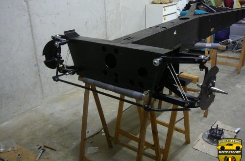
After welding it up we can check the fitment with our new adjustable lower links that I made before.

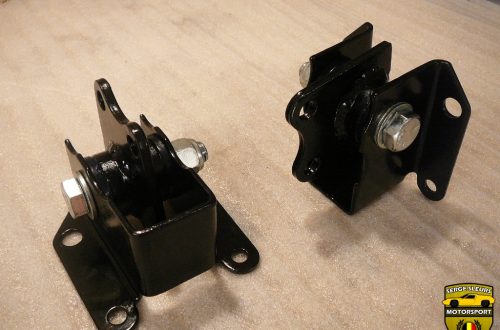
Some Epoxymastic paint, and they are ready to be used once again.
This was a very long post, I hope it was interesting enough to get to the end. A new video on this part of the restoration will find it’s way online in the future. In the meantime you can watch the rest of the video series by clicking here.
Enjoy & Share,
Serge